Model No.: RFCT-17201
Curriculum Outline:
1. Design and implementation of RF front end receiver module.
2. Design and implementation of RF front end transmitter module.
3. Design and implementation of voltage controlled oscillator and phase lock loop.
4. Design and implementation of IF demodulator and audio process circuit.
5. Design and implementation of wireless transceiver module.
Features
Curriculum Objectives:
1. Training for wireless communication technicians and engineers.
2. To understand the applications and measurements of communication instruments and products.
3. Design and implementation ability training for RF module circuit.
4. To shorten the gap between academic and industrial circles.
Specifications:
Module One: RFCT-17201-01
Chapter 1 Elementary Impedance Matching Network
Experiment 1: L-Type Matching Network (Operational Frequency: 900 MHz)
Experiment 2: PI-Type Matching Network (Operational Frequency: 900 MHz)
Experiment 3: T-Type Matching Network (Operational Frequency: 900 MHz)
Chapter 2 Impedance Matching Network
Experiment 1: Tapped Capacitor Matching Network
(Operational Frequency: 900 MHz)
Experiment 2: Tapped Inductor Matching Network
(Operational Frequency: 900 MHz)
Experiment 3: Low Quality Factor Matching Network
(Operational Frequency: 900 MHz)
Module Two: RFCT-17201-02
Chapter 3 One Stages Low Noise Amplifier
Experiment 1: Measurement of Frequency Responses
(Operational Frequency: 890 ~ 915 MHz)
Experiment 2: Measurement of Noise Figure
(Operational Frequency: 890 ~ 915 MHz; Noise Figure: 2 dB)
Experiment 3: Measurement of 1-dB Compression Point
(Operational Frequency: 890 ~ 915 MHz; P : -10 dBm)
Chapter 4 Two Stages Low Noise Amplifier
Experiment 1: Measurement of Frequency Responses
(Operational Frequency: 890 ~ 915 MHz)
Experiment 2: Measurement of Noise Figure
(Operational Frequency: 890 ~ 915 MHz; Noise Figure: 2 dB)
Experiment 3: Measurement of 1 dB Compression Point
(Operational Frequency: 890 ~ 915 MHz; P : -10 dBm)
Module Three: RFCT-17201-03
Chapter 5 Two Stages Pre-amplifier
Experiment 1: Measurement of Frequency Responses
(Operational Frequency: 800 ~ 1000 MHz)
Experiment 2: Measurement of Noise Figure
(Operational Frequency: 800 ~ 1000 MHz; Noise Figure: 3 dB)
Experiment 3: Measurement of 1 dB Compression Point
(Operational Frequency: 800 ~ 1000 MHz; P : -5 dBm)
Chapter 6 Power Amplifier
Experiment 1: Measurement of Gain Flatness
(Operational Frequency: 700 ~ 1000 MHz; Gain Flatness: ±2.5 dB)
Experiment 2: Measurement of 1 dB Compression Point
(Operational Frequency: 700 ~ 1000 MHz; P : 15 dBm)
Experiment 3: Measurement of OIP3
(Operational Frequency: 915 MHz; IP3: 25 dBm)
Experiment 4: Measurement of Harmonics (Operational Frequency: 915 MHz)
Module Four: RFCT-17201-04
Chapter 7 Colpitts and Hartley Oscillators
Experiment 1: Measurement of Frequency and Output Power
(Oscillation Frequency: 800 ~ 900 MHz)
Experiment 2: Measurement of Phase Noise (Phase Noise: -90 ~ -110 dBc/Hz)
Experiment 3: Measurement of Gain Factor and Variable Bandwidth
(Gain Factor: 10 ~ 14 Mhz/V; Variable Bandwidth: 50 ~ 70 MHz)
Chapter 8 Common Collector Colpitts Oscillator
Experiment 1: Measurement of Frequency and Output Power
(Oscillation Frequency: 750 ~ 850 MHz)
Experiment 2: Measurement of Phase Noise (Phase Noise: -90 ~ -110 dBc/Hz)
Experiment 3: Measurement of Gain Factor and Variable Bandwidth
(Gain Factor: 8 ~ 10 MHz/V; Variable Bandwidth: 40 ~ 50 MHz)
Module Five: RFCT-17201-05
Chapter 9 Microcontroller for Phase Lock Loop
Experiment 1: LCD and Keypad Testing
(Locked Frequency Display; Locked Status Detection)
Experiment 2: MB15E03L Control Signal Testing
(Locked Frequency: 812 MHz; 825 MHz; 850 MHz)
Chapter 10 Phase Locked Loop
Experiment 1: Measurement of Frequency Responses for Loop Filter
(-3 dB Frequency: 600 Hz)
Experiment 2: Measurement of PLL
(Locked Frequency: 812 MHz; 825 MHz; 850 MHz)
Experiment 3: Measurement of FM Signal
(Audio Signal: 1 kHz; Modulation Bandwidth: 100 ~ 150 kHz)
Module Six: RFCT-17201-06
Chapter 11 Diode Mixer
Experiment 1: Measurement of Conversion Gain
(Radio Signal: 795 ~ 895 MHz or 1800 ~ 1900 MHz; Local Signal: 915 MHz or 1780 MHz;
Intermediate Signal: 20 ~ 100 MHz)
Experiment 2: Measurement of 1 dB Compression Point
(Radio Signal: 845 MHz or 1850 MHz; Local Signal: 915 MHz or 1780 MHz;
Intermediate Signal: 70 MHz)
Experiment 3: Measurement of Isolation
(Local Signal: 840 ~ 990 MHz or 1705 ~ 1855 MHz)
Chapter 12 Transistor Mixer
Experiment 1: Measurement of Conversion Gain
(Radio Signal: 877 ~ 977 MHz or 910 ~ 1010 MHz; Local Signal: 857 MHz or 850 MHz;
Intermediate Signal: 20 ~ 100 MHz or 60 ~ 160 MHz)
Experiment 2: Measurement of 1 dB Compression Point
(Radio Signal: 927 MHz or 910 MHz;
Local Signal: 857 MHz or 850 MHz: Intermediate Signal: 70 MHz or 60 MHz)
Experiment 3: Measurement of Isolation
(Local Signal: 782 ~ 932 MHz or 840 ~ 990 MHz)
Module Seven: RFCT-17201-07
Chapter 13 Low-pass and High-pass Filters
Experiment 1: Measurement of Frequency Responses
(Operational Frequency: 500 ~ 1500 MHz; Low-pass -3 dB Frequency: 900 MHz;
High-pass -3 dB Frequency: 900 MHz)
Chapter 14 Band-stop and Band-pass Filters
Experiment 1: Measurement of Frequency Response
(Operational Frequency: 500 ~ 1500 MHz; Band-stop Center Frequency: 900 MHz;
Bandwidth: 200 MHz; Band-pass Center Frequency: 70 MHz; Bandwidth: 20 MHz)
Module Eight: RFCT-17201-08
Chapter 15 IF FM Demodulation Circuit
Experiment 1: Measurement of IF FM Demodulation Circuit
(Intermediate Signal: 70.7 MHz, Modulation Bandwidth: 20 kHz)
Chapter 16 Audio Signal Process Circuit
Experiment 1: Measurement of Pre-emphasis and Compression for Audio Signal
(Audio Signal: 20 Hz ~ 50 kHz)
Experiment 2: Measurement of De-emphasis and Decompression for Audio Signal
(Audio Signal: 20 Hz ~ 50 kHz)
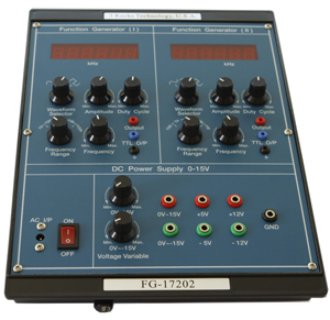
Optional Function Generator/ Power Supply module: FG-17202
Power Supply: 4 fixed voltage outputs(+/- 5V, +/- 12V), 2 variable voltage outputs (+/- 0 ~15 V)
Low ripple and noise
Function Generator:
Output: 2 CHs
Frequency Range: 10 Hz ~ 100 KHz, 100Hz ~ 1 MHz
Waveforms: TTL pulse, Square, Triangle, and Sinewave
Amplitude: 10 Vp-p
2 built-in 6-digit frequency counters
Overload protection
* Oscilloscope, function generator, power supply, Spectrum analyzer are not included.