Model No.: FEPE-21604
FPGA Control Module
1. 1000k FPGA programmable logic gates with energy & power electronics control drivers
2. 16-bitTI-MSP 430 Microcontroller
3. USB interface
4. 128KB RAM
5. 512KB Flash ROM and FPGA control circuits
6. CMOS digital video driver interface
7. ZigBee wireless communication interface
8. 50-pin double row connector to connect the energy system and power electronic control module
9. Optical fiber I/O interface, providing up to 31 groups of synchronized real-time connection
Energy Systems and Power Electronics Control Module
1. 50-pin double row connector
2. Lithium battery, nickel-cadmium battery, nickel metal hydride battery and lead acid battery charging and discharging control circuit
3. Solar control and conversion circuits, one set of solar panel.
4. Wind turbine charger control and conversion circuit, and one set of wind turbine generation module
5. 2 sets of optical disc decoding circuit
6. 16 sets of servo control circuit and two servos
7. one set of PWM driver and two DC motors
8. 2 sets of LED driver control circuit
9. 2 sets of SPWM modulation driver control circuit
Servo Driver Module
1. 2 sets of 0~180° position control servo with a fixture
2. Connected to the power electronic control module
DC Motor Module
1. 2 sets of 12V, 200 RPM DC gear motors with a fixture
2. Connected to the power electronic control module
Power Driver Module
1. 2 sets of 3 x 5 white LED array
2. 2 sets of 5W AC power lamp
ZigBee Wireless Communication Module
1. CC2420 chip
2. RF configuration based onthe IEEE 802.15.4 specifications
3. Wireless network by the master node and 30 nodes in the network connection auxiliary
4. Effective transmission range upto 50 meters in an open area
5. Connected to the power electronics control module
CMOS Digital Video Module
1. 640 x 480 pixels
2. 16-bit RGB color ouput
3. Adjustable focal length lens
4. Connected to the power electronics control module
System Software
1. VHDL development environment and USB interface for downloading drivers
2. C and assembly language editor, compiler
3. ZigBee wireless communication real-time monitoring and settings
4. Fiber optic communications network for real-time monitoring and settings
5. Experiments included in the system:
a. Lithium battery charging experiment
b. Solar battery charging experiment
c. LED dimming control experiment
d. SPWM DC to AC experiment
e. DC motor control experiment
f. Servo position control experiment
g. Select the lens and the target color
h. Color filter and parameter adjustment
i. Point targets and servo control experiment
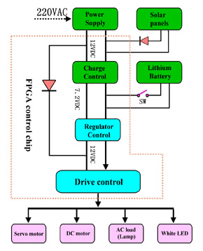
Energy Systems & Power Electronics Software Control Flow Chart