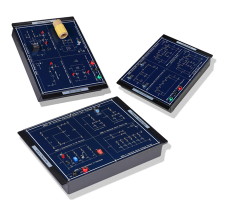
Electronics and Electricity Trainer, Model No.: EET-17015
Curriculum Outline:
1. DC sources, Switches, Ohm's Law, Voltage divider
2. Series, parallel, series-parallel circuits
3. DC and AC circuits of basic electronics and electricity
4. Kirchhoff's Law, Thevenin's theorem, and Norton's theorem
5. Magnetic field circuits and Ampere's law
6. Fleming's rule and Faraday's Law
Module One: EET-17015-01
Chapter 1: DC sources, Switches, Ohm's Law, Voltage Divider
Experiment 1: Introduction to DC sources (DC Sources: 1.5V; Series and Parallel DC sources)
Experiment 2: Introduction to Switches (Types of switch: Push Button Switch, DIP Switch, Toggle Switch, Rocker Switch, LED Display)
Experiment 3: Ohm's Law (Fixed voltage: 5V, Fixed Current: 5 mA)
Experiment 4: Voltage Divider (Input voltage: 5V, 8 Resistors)
Module Two: EET-17015-02
Chapter 2: Series, Parallel, and Series-Parallel Resistive Circuits
Experiment 1: Series Resistive Circuits (2 to5 Series Resistors)
Experiment 2: Parallel Resistive Circuits (2 to 5 Parallel Resistors)
Experiment 3: Series-Parallel Resistive Circuits (3 to 5 Series-Parallel Resistors)
Module Three: EET-17015-03
Chapter 3: DC Circuits of Basic Electronics and Electricity
Experiment 1: Superposition Theorem (Input Voltage: 12V. -12V, 7 resistors)
Experiment 2: ∆ and Y Transforms (4 sets, 3 Resistors for each set)
Experiment 3: Dependent Sources (VCVS: adjustable voltage from 0 to 3V; CCCS: adjustable current from 0.1 to 3 mA)
Experiment 4: Wheatstone Bridge (Input Voltage: 12V, 10 resistors)
Module Four: EET-17015-04
Chapter 4: AC Circuits of Basic Electronics and Electricity
Experiment 1: RC Series Circuits (fin=100 Hz to 2.4 kHz)
Experiment 2: RL Series Circuits (fin=10 kHz to 350 kHz)
Experiment 3: LC Series Resonance Circuits (fin=5 kHz to 100 kHz)
Experiment 4: LC Parallel Resonance Circuits (fin=5 kHz to 80 kHz)
Experiment 5: RLC Filter Circuits (fin=100 Hz to 360 kHz)
Module Five: EET-17015-05
Chapter 5: Kirchhoff's Law, Thevenin's Theorem, Norton's Theorem
Experiment 1: Kirchhoff's Current Law (Iin1= 5mA, Iin2=-5mA, Iin3=10mA)
Experiment 2: Kirchhoff's Voltage Law (Vin1=12V, Vin2=5V, Vin3=-12V)
Experiment 3: Thevenin's Theorem and Norton's Theorem (Vin1=12V, Vin2=5V, Vin3=-5V, Vin4=-12V)
Experiment 4: Node Voltage and Mesh Current (Vin1=12V, Vin2=5V, Vin3=-5V, Vin4=5V, Vin5=-5V, Vin6=-12V)
Module Six: EET-17015-06
Chapter 6: Magnetic Field and Ampere's Law
Experiment 1: Magnetic Reed Sensor Circuit
(Vin=5V, Use a magnet to control magnetic reed sensor ON or OFF)
Experiment 2: Magnetic Relay Circuit
(Vin=5V, 12V, Use a magnet to control magnetic relay circuit ON or OFF)
Experiment 3: Magnetic Hall Effect Sensor Circuit
(Vin=5V, LED display, Use a magnet to identify N-S magnetic poles)
Experiment 4: Ampere's Law Application Circuit
(AC Input, Vin=12V,-12V; Iin=0 to 0.75A, Use a magnet to generate N-S magnetic field)
Module Seven: EET-17015-07
Chapter 7: Fleming's Rule and Faraday's Law
Experiment 1: Fleming's Rule of electromagnetic induction ( Electronic Motor, Vin=1.5V)
Experiment 2: Faraday's Law of electromagnetic induction (Inductive voltage: -15mV ~ 15mV)
Module Eight: EET-17015-08
Chapter 8: Semiconductors for basic electronics and electricity
Experiment 1: Diode Characteristics Circuits (Vin=12V, -12V, Vout=-12V ~ 0.7V)
Experiment 2: Zener Diode Characteristics Circuits (Vin=12V, -12V; Vout=-0.7 V ~ 5V)
Experiment 3: BJT Basic Application Circuits (Vin=12V; BJT turns ON or OFF)
Experiment 4: OPA Basic Application Circuits (Inverting Amplifier's Gain:2; Noninverting Amplifier's Gain:3)