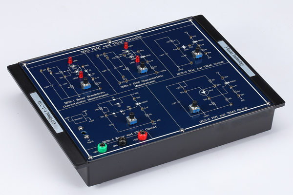
Model No.: IECT-17060
Curriculum Objectives
* Introduction to the fundamental theories of industrial electronics circuits
* Design and implementation of thyristor and transistor
* Introduction to the industrial electronics circuits applications
 Curriculum Outlines
* Design and implementation of UJT and PUT thyristor circuits
* Design and implementation of SCR, TRIAC, and DIAC thyristor circuits
* Design and implementation of SCS, GTO, SBS, and SSR thyristor circuits
* Design and implementation of MOSFET, BJT, and IGBT transistor circuits
* Design and implementation of temperature sensors and optical elements circuits
Module One: IECT-17060-01
Chapter 1: UJT and PUT circuits
Experiment 1: UJT Volt-ampere characteristic curve measurement
(Vin = 3~9 V, Iout= 1.6 ~ 11.5 mA)
Experiment 2: UJT Relaxation Oscillator
(fout=120Hz ~ 1.2KHz)
Experiment 3: UJT Equivalent Circuit
(Vin = 3 ~ 7V)
Experiment 4: PUT Volt-Ampere characteristic curve measurement
( Iout = 142Hz ~ 1.37KHz)
Module Two: IECT-17060-02
Chapter 2: SCR and GTO Circuits
Experiment 1: SCR Characteristic measurement
(Forward: SCR on @ = 0 ~0.8V, Reverse: SCR off @= 0 ~ 12V)
Experiment 2: SCR Phase angle controlled circuit
(Phase angle: 0° ~ 70°)
Experiment 3: Zener and SCR circuit
(Phase angle: 40° ~ 70°)
Experiment 4: GTO Characteristic circuit
(Use a switch to control GTO On/ Off)
Experiment 5: GTO Oscillation circuit
(fout = 185.2 Hz)
Module Three: IECT-17060-03
Chapter 3: DIAC and TRIAC circuits
Experiment 1: Zener breakdown characteristic measurement
(Forward breakdown: 5.1V, Reverse breakdown: -5.19V)
Experiment 2: DIAC characteristic measurement
(Forward breakdown: 24.4V, Reverse breakdown: -23.2V)
Experiment 3: DIAC and TRIAC circuits
(Phase angle: 0° ~ 85°)
Experiment 4: Zener and TRIAC circuits
(Phase angle: 10° ~ 30°)
Experiment 5: PUT and TRIAC circuits
(fout = 82 ~ 174 Hz)
Module Four: IECT-17060-04
Chapter 4: SCS and SSR circuits
Experiment 1: SCS characteristic measurement
(Use a switch to control SCS On/ Off)
Experiment 2: SCS equivalent circuit
(Use BJT to complete SCS equivalent circuit)
Experiment 3: SCS and SCR circuits
(Use switches to control SCS and SCR On/ Off)
Experiment 4: SSR DC output circuit
(Use DC to control output, Output voltage mode: DC)
Experiment 5: SSR AC output circuit
(Use DC to control output, Output voltage mode: AC)
Module Five: IECT-17060-05
Chapter 5: SBS circuits and temperature sensors
Experiment 1: SBS characteristic measurement
(SBS voltage forward: 9 ~ 10V, SBS voltage reverse: -9 ~ -10V)
Experiment 2: SBS and TRIAC circuit
(Phase angle: 30° ~ 85°)
Experiment 3: Temperature sensor using SCR and LM335
(Use LM335 to control SCR On/ Off, Output voltage mode: DC)
Experiment 4: Temperature sensor using SCR and TC620
(Use TC620 to control SCR On/ Off, Output voltage mode: AC)
Module Six: IECT-17060-06
Chapter 6: Optical elements and application circuits
Experiment 1: Photoresistor circuit
(Use CdS to control LED On/ Off)
Experiment 2: Photocoupler circuit
(Use DPI0501 to control LED On/ Off)
Experiment 3: Photointerrupter circuit
(Use DPI0501 to control LED On/ Off)
Experiment 4: Photodiode circuit
(Use HPDB5-14D to control LED On/ Off)
Experiment 5: Phototransistor circuit
(Use RCPT3E850 to control LED On/ Off)
Module Seven: IECT-17060-07
Chapter 7: MOSFET characteristic and application circuits
Experiment 1: MOSFET characteristic measurement
(VG= 0 ~ 4V, ID=0 ~ 2.15mA, IG=0uA)
Experiment 2: MOSFET regulator
(VOUT = 1 ~ 6V)
Experiment 3: MOSFET full bridge circuit
(Use MOSFET to control the current direction Forward/ Reverse)
Experiment 4: MOSFET PWM controlled circuit
(Output duty cycle: 10% ~ 90% @410Hz)
Experiment 5: MOSFET and PUT circuits
(Output duty cycle: 10% ~ 90% @PUT output frequency 4.08KHZ ~ 7.27KHZ)
Module Eight: IECT-17060-08
Chapter 8: BJT and IGBT circuits
Experiment 1: BJT characteristic measurement
(VG = 0 ~ 4V, IC = 0 ~ 3.27mA, IG = 0uA)
Experiment 2: BJT PWM controlled circuit
(Output duty cycle: 10% ~ 90%@6.14KHz)
Experiment 3: BJT full bridge circuit
(Use BJT to control current direction: forward/ reverse)
Experiment 4: IGBT characteristic measurement
(VG = 0 ~ 6V. ID = 0 ~ 1.68mA, IG = 0uA)
Experiment 5: IGBT PWM controlled circuit
(Output duty cycle: 10% ~ 90% @24Hz)
Module Nine: IECT-17060-09
Chapter 9: SCR/SCS/DIAC/TRIAC circuits
Experiment 1: SCR application circuit
(Phase angle: 10° ~ 85°)
Experiment 2: CdS and SCR application circuit
(Use CdS and SCR to control SCR On/ Off)
Experiment 3: DIAC and TRIAC application circuit
(Use DIAC and TRIAC to control AC output)
Experiment 4: SCS and SCR application circuit
(Use switches to control SCS and SCR On/ Off)
