Model No.: FDCT-21606
FPGA Digital Communication Interface Module
1. 1000K FPGA programmable logic gates controlled by piDSP chip
2. USB interface for parameters setting and real-time control
3. 12-bit 2-CH ADC with 1 MHz sampling rate
4. 12-bit 2-CH DAC with 1 MHz sampling rate
5. 128KB RAM and 512KB Flash ROM
6. 26-pin output interface to provide 16 sets of I/O and 1 set of AD/DA I/O port
7. 4-digit 7-segment display
8. 4x4 matrix keyboard
9. 16 I/O with LED display
10.Fiber optical I/O interface, providing upto 31 sets synchronized control
Fiber Optics and Radio Communication Module
1. Radio transmitter.
2. Radio receiver circuits.
3. Fiber optics communications interface
4. TTL/CMOS interface
5. RS232/RS422 interface
Remote Control and Telephone Interface Module
1. Infrared transmitter circuit
2. Infrared receiver circuit
3. Telephone communications interface
4. TV remote control set
5. Telephone set
System Software
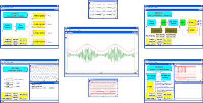
1. System operation designed by FPLC graphic control system
2. Illustration tools includes shapes, lines, characters
3. Dynamic simulation symbols include meters, display lights, oscilloscopes, transducers, push-buttons,..
4. Select your own jpg file as the background for the monitoring screen
5. 4-channel oscilloscopes for real-time display
6. 16-channel 24MB logic analyzer for real-time display
7. FPGA with DSP power electronics control chip which can be re-planned and re-designed
8. Fiber optics interface can be used for synchronized communication to execute the FPGA data. The data exchange rate is upto 1KHz.
9. Experiments included in the software system:
10. Experiments included in the system software:
Experiment 1: Introduction to analog signals (AM/ FM/ PM)
a. The basic waveforms generator (sine wave, sawtooth, pulse-width modulation wave)
b. Frequency Modulation
c. Amplitude Modulation
d. Phase Modulation
e. Mixed signal
Experiment 2: Introduction to digital signals (NRZ/Manchester)
a. Handle unipolar
b. NRZ polar processing (NRZ-L, NRZ-I)
c. RZ polar processing
d. Two-phase polar processing (Manchester, Diff-Manchester)
e. Handle bipolar (AMI, B8ZS, HDB3)
Experiment 3:Digital filter design (IIR)
a. Low-pass filter experiment
b. High-pass filter experiment
c. Band-pass filter experiment
Experiment 4:Digital filter design (FIR)
a. Low-pass filter experiment
b. High-pass filter experiment
c. Band-pass filter experiment
Experiment 5: Phase-Lock-Loop design (PLL)
a. Phase detect experiment
b. Simple phase lock loop experiment
c. Double frequency experiment
Experiment 6: UART interface design (RS232/RS422)
a. The basic interface testing
b. Random number statistical test
Experiment 7: Infrared Ray (IR) interface design (NEC specs)
a. IR receiver test
b. IR transmitter test
Experiment 8: Radio frequency (RF) interface design
a. RF radio interface test(HT12 specs)
b. IR infrared interface test (HT12 specs)
Experiment 9:Fiber optics interface design
a. SPDIF interface test
b. Dual-channel communication test
Experiment 10: Telephone voice interface (DTMF specs)
a. DTMF decoding

