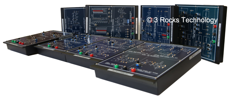
Analog Communication Trainer, Model No.: ACT-17300
Features:
1. To understand the basic theory of analog communication systems.
2. Design and implementation ability training of analog modulators and demodulators.
3. To understand the applications of analog modulators and demodulators.
Curriculum Outlines:
1. Design and implement second-order active filters and RF oscillators.
2. Design and implement AM and FM modulators and demodulators.
3. Design and implement DSB/SC and SSB modulators and demodulators.
4. Design and implement TDM and FDM multiplexer and demultiplexer.
5. Design and implement frequency converter and signal recovery circuits.
Specifications:
Module One: ACT-17300-01
Chapter 1: Second-Order Active Filters
Experiment 1: Second-order Active Low-pass Filter (Low-pass -3db, Frequency: 1 kHz ~ 3kHz)
Experiment 2: Second-order Active High-pass Filter (High-pass -3db, Frequency: 5 kHz ~ 10kHz)
Experiment 3: Second-order Active Band-pass Filter (center Frequency: 10 kHz ~ 100 kHz, Bandwidth: 6 kHz ~ 60 kHz)
Experiment 4: Second-order Active Band-stop Filter (Cutoff Frequency: 10 kHz ~ 100 kHz, Bandwidth: 6 kHz ~ 60 kHz)
Chapter 2: RF Oscillators
Experiment 1: Colpitts Oscillator (Oscillation Frequency: 1 MHz ~ 9 MHz)
Experiment 2: Hartley Oscillator (Oscillation Frequency: 500 kHz ~ 1.8 MHz)
Experiment 3: Crystal Oscillator (Oscillation Frequency: 6 MHz)
Experiment 4: Voltage Controlled Oscillator (Oscillation Frequency: 3.5 MHz ~ 4 MHz)
Module Two: ACT-17300-02
Chapter 3: AM Modulator
Experiment 1: Transistor AM Modulator (Carrier Signal: 100 kHz ~ 500 kHz, Audio Signal: 500 Hz ~ 1 kHz)
Experiment 2: MC1496 AM Modulator (Carrier Signal: 500 kHz ~ 1 MHz, Audio Signal: 500 Hz ~ 1 kHz)
Chapter 4: AM Demodulator
Experiment 1: AM Diode Detector (Carrier Signal: 300 kHz, Audio Signal: 500 Hz ~ 2 kHz)
Experiment 2: AM Product Detector (Carrier Signal: 500 kHz ~ 1 MHz, Audio Signal: 500 Hz ~ 1 kHz)
Module Three: ACT-17300-03
Chapter 5: DSB-SC and SSB Modulator
Experiment 1: DSB-SC Modulator (Carrier Signal: 100 kHz ~ 500 kHz, Audio Signal: 500 Hz ~ 1 kHz)
Experiment 2: SSB Modulator (Carrier Signal: 200 kHz, Audio Signal: 500 Hz ~ 1 kHz)
Chapter 6: DSB-SC and SSB Demodulator
Experiment 1: DSB-SC Product Detector (Carrier Signal: 100 kHz ~ 500 kHz, Audio Signal: 500 Hz ~ 1 kHz)
Experiment 2: SSB Product Detector (Carrier Signal: 200 kHz, Audio Signal: 500 Hz ~ 1 kHz)
Module Four: ACT-17300-04
Chapter 7: FM Modulator
Experiment 1: MC4046 FM Modulator (Carrier Signal: 20 kHz, Audio Signal: 1 kHz)
Experiment 2: SN74124 FM Modulator (Carrier Signal: 20 kHz, Audio Signal: 1 kHz ~ 1.5 kHz)
Chapter 8: FM Demodulator
Experiment 1: MC4046 FM Demodulator (Carrier Signal: 20 kHz, Audio Signal: 1 kHz)
Experiment 2: LM565 FM Demodulator (Carrier Signal: 20 kHz, Audio Signal: 1 kHz ~ 1.5 kHz)
Module Five: ACT-17300-05
Chapter 9: TDM Multiplexer
Experiment 1: Waveform Generator
(Sine Wave Signal Generator: 13 kHz, Triangle Wave Signal Generator: 2.3 kHz, Square Wave Signal Generator: 2.3 kHz)
Experiment 2: TDM Multiplexer (Transmission Channels: 3 Channels, Switching Time: 500 ms ~ 50 ms)
Chapter 10: TDM Demultiplexer
Experiment 1: TDM Demultiplexer (Transmission Channels: 3 Channels, Switching Time: 500 ms ~ 50 ms)
Module Six: ACT-17300-06
Chapter 11: FDM Multiplexer
Experiment 1: FDM Signal Generator (Carrier Signal: 100 kHz ~ 1.1 MHz, Audio Signal: 500 Hz ~ 1.5 kHz)
Experiment 2: DSB-SC Modulated Signal Generator (Carrier Signal: 100 kHz ~ 1.1 MHz, Audio Signal: 500 Hz ~ 1.5 kHz)
Experiment 3: FDM Multiplexer
Chapter 12: FDM Demodulator
Experiment 1: FDM Demultiplexer (Modulation Type: DSB-SC Signal, Demultiplexing Tpye: Product Demultiplexer)
Module Seven: ACT-17300-07
Chapter 13: Analog-to-digital Converter
Experiment 1: ADC0804 Analog-to-digital Converter (Resolution: 8 bits, Analog Input Voltage: 0 V ~ 5 V)
Experiment 2: ADC0809 Analog-to-digital Converter (Resolution: 8 bits, Analog Input Voltage: 0 V ~ 5 V, Clock Frequency: 120 kHz)
Chapter 14: Digital-to-analog Converter
Experiment 1: R-2R Digital-to-analog Converter (Digital Input: 4 bits, Analog Output: 0 V ~ 5 V)
Experiment 2: Unipolar DAC 0800 Digital-to-analog Converter (Digital Input: 8 bits, Analog Output: 0 V ~ 5 V, Step Value: 0.019 V)
Experiment 3: Bipolar DAC 0800 Digital-to-analog Converter (Digital Input: 8 bits, Analog Output: -5 V ~ 5 V, Step Value: 0.038 V)
Module Eight: ACT-17300-08
Chapter 15: Frequency Converter
Experiment 1: Frequency Multiplier (Carrier Signal: 10 kHz)
Experiment 2: Up/Down Frequency Converter (Carrier Signal @LO port: 100 kHz, Carrier Signal @ RF port: 120 kHz)
Chapter 16: Signal Recovery
Experiment 1: Carrier Signal Recovery Circuit (Carrier Signal: 10 kHz)
Experiment 2: Clock Recovery Circuit (Clock Signal: TTL, Encoded Signal: Manchester, Clock Frequency: 5 kHz ~ 10 kHz)
Optional Function Generator/ Power Supply module: FG-17202
Power Supply: 4 fixed voltage outputs(+/- 5V, +/- 12V), 2 variable voltage outputs (+/- 0 ~15 V)
Low ripple and noise
Function Generator:
Output: 2 CHs
Frequency Range: 10 Hz ~ 100 KHz, 100Hz ~ 1 MHz
Waveforms: TTL pulse, Square, Triangle, and Sinewave
Amplitude: 10 Vp-p
2 built-in 6-digit frequency counters
Overload protection
* Oscilloscope, function generator, power supply are not included.