Model No.: DSL-32608
Features:
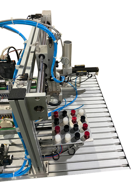
This trainer provides an environment for the students to practice how to utilize a servo motor, stepper motor, and potentiometer for industrial control application.
The "barrels" with 3 different heights (0.7", 0.8", and 0.9") are distributed to a checking point. A potentiometer checks their heights. Based on the results, a gantry-type distribution system, powered by pneumatics and a servo motor, delivers them to a 4x4 mobile "pallet".
Specifications:
1. Distribution & Sorting Module
(a). The "barrel" distribution system accommodates up to 8 "barrels". The barrels are represented by the circular parts (ø20 mm) with different colors (red, black), materials (plastic, metal), and heights(0.7", 0.8", 0.9").
Red metal parts (0.7", 0.8", and 0.9") 4 pieces each, black metal parts (0.7", 0.8", and 0.9") 4 pieces each, and white plastic parts (0.7", 0.8" and 0.9") 4 pieces each. In total, there are 36 parts.
(b). The distribution module is powered by a compact pneumatic cylinder (ø12 mm x 75 mm).
(c). The height, color, and material are detected after the part is pushed to the part detection area.
(d). The potentiometer( 4-20 mA) is driven by a rotary actuator to check the height of the "barrel".
2. Gantry-type Distribution Mechanism Module
(a). The horizontal movement is driven by a screw-rod (ø16 mm) mechanism and powered by an AC servo motor.
(b). Two double-row ball bearings are installed on both ends of the screw to provide precise and smooth movement.
(c). Two critical limit switches are installed on both ends of the gantry type distribution mechanism for safety.
(d). The vertical movement is provided by a dual rod cylinder (ø16 mm x 70 mm) with two flow regulators.
(e). Double acting, parallel gripper (ø16 mm) with two flow regulators.
3. 4x4 Mobile Pallet Platform
(a). A screw with a dual guide rod mechanism. Two critical limit switches are installed on both ends for safety.
(b). A photo interrupt sensor is used for the mobile platform's home position.
(c). The pallet platform is driven by a stepper motor that is connected to the screw by a flexible coupling.
(d). The 4x4 mobile pallet platform size is 6"x6". It has 16 evenly spaced blind holes (ø21 mm x 3 mm ) with a chamfered edge.
4. Aluminum Platform & Box Shaped Steel Structure
(a). Aluminum platform size is 24" x 18". There are T-shape slots 30 mm apart which are used for affixing the mechanism modules.
(b). Box-shaped steel structure size is 24"x18"x12". A drawer control unit with a safety latch is installed in the box steel structure.
(c). Both servo drive and stepper drive are affixed on the platform right next to the motors.
(d). All input wires are connected to a 25-pin male D-sub connector. All output wires are connected to a 25-pin female D-sub connector. AC110V, DC24V, and DC10V are connected to a 5-pin connector.
5. Solenoid Valve Set, Air Source Unit
(a). Air filter & pressure regulator set
(b). 4-position air manifold
(c). 5W/2P single solenoid valve with spring offset x 3 pcs.
(d). 5W/2P double solenoid valve x 1 pc
6. Control Panel & PLC
(a). Allen Bradley 800 series PLC or equivalent, 2 analog inputs and 2 100KHz pulse outputs
(b). Push button x 4pcs, 2-position selector switch x 1pc, 3-position selector switch x 1pc, Red lamp x 1pc, Amber lamp x 1pc, Start push button x 1pc, Stop push button x 1pc, Emergency Stop Switch #1(Turn off the system power) x 1pc, Emergency Stop Switch #2(Turn the output devices off).
(c). The control panel, PLC, and power supplies(DC24V & DC10V) are installed on the drawer of the box-shaped steel structure.
(d). The AC 110V switch is installed on the control panel.
(e). PLC I/O terminals are connected to the Extended I/O terminal blocks. All inputs on the extended input terminal block are connected to the 25-pin male D-sub connector module. All outputs on the extended output terminal block are connected to the 25-pin female D-sub connector module. AC 110V, DC 24V, and DC10V are connected to the 5-pin module.
Labs:
Fundamental:
1. Distribution Control, Continuous Cycle
2. Sensor Detection Control (I)
3. Sensor Detection Control (II)
4. Gantry-Type Robotic Arm Loading/ Unloading Control
5. Servo Motor Fwd./ Rev. Control
6. Servo Motor Positioning Control
7. Servo Motor Speed Control
8. Stepper Motor Fwd./ Rev. Control
9. Stepper Motor Positioning/ Speed Control
10. Distribution Loading/ Unloading Control- Single Cycle
Advanced:
11. Distribution Loading/ Unloading Control- Continuous Cycle (I)
12. Distribution Loading/ Unloading Control- Continuous Cycle (II)
13. Distribution Loading/ Unloading Control- Continuous Cycle (II)